Difference between revisions of "Your first tile assembly"
| Line 22: | Line 22: | ||
[[File:New_tile_color.png|thumb||center|upright=4.0|alt=Adding Color]] | [[File:New_tile_color.png|thumb||center|upright=4.0|alt=Adding Color]] | ||
| + | |||
| + | ====Seeding & Simulating the Blob==== | ||
| + | Now it is time to load your tile into the Simulation Space. To do this navigate to the TAS Simulation Window, locate the toolbar, and click the curved arrow (labeled as 'A' in the picture below) that is pointing to the left. This arrow will load the current tileset from the Tileset Editor, although it will not place a tile. To place a tile, right click a square in the Simulation Space, a box will appear containing a list of the tiles you can place, select a tile. In this case we only have one tile loaded so that will be our only option. | ||
| + | |||
| + | [[File:Arrow_a.png|thumb||center|upright=4.0|alt=ArrowA]] | ||
| + | |||
| + | There are a couple of important points to consider about placing tiles in the Simulation space. The first point is that the first tile or tiles you place before you increment the assembly forward is called the '''seed''' of the assembly. You can think of the '''seed''' just like you might think about the seed of a plant, it is the source from which the other parts of the assembly grow. The second important point is that after you place your seed tile(s) and increment the assembly forward, you cannot place any new tiles in the Simulation space until you restart the assembly. | ||
Revision as of 12:23, 9 August 2013
Contents
Introduction
Growth
An important concept in tile based assembly is how an assembly grows. In this tutorial you will be introduced to examples of the two major growth classes: undirected and directed. For our undirected system we will create a single-tile that when placed in the simulation space will grow in a random and undirected fashion. In response to the cancerous-blob we've created we will then build several new tiles that will act as a fence to encapsulate the blob. The fence tiles will be an example of a directed system. They will only grow where and as far as we want them to.
The Undirected Uni-tiled Blob
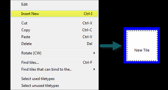
Before we can witness our Blob assembling in the Simulation Window we must first create a tile in the Tileset Editor window. Luckily because our Blob is a simpleton he consists only of a single tile. To create a tile right click in the Tiletype editor and select Insert New.
A tile will appear in the editor with a blue square around it. Whenever this blue square is around a tile in the Tiletype editor it means that this tile is currently selected and that you may edit its features in the Tile Type Definition window.
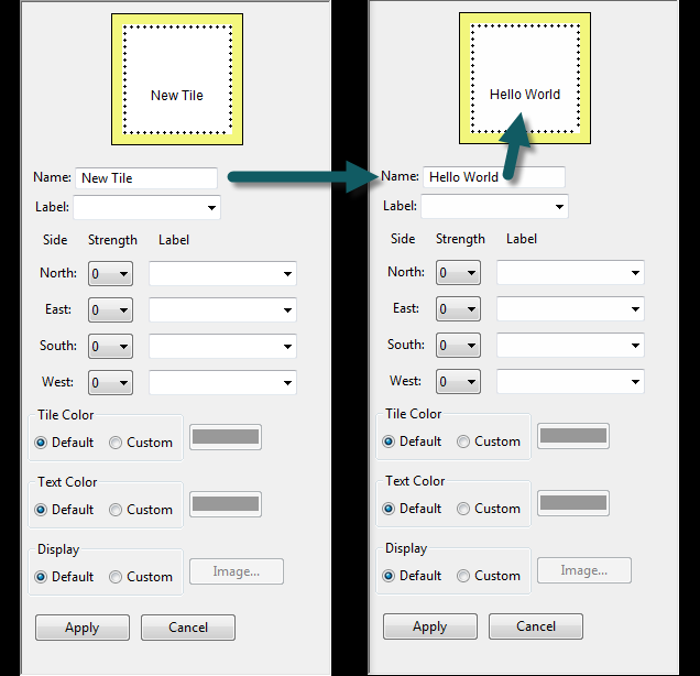
Now it is time to give your tile a name. I will call mine Hello World, but you may name your tile as you please. Strictly speaking, a tile name will not affect how your tiles will assemble. Tile names are simply a way for you to recognize and organize your tiles and tile sets. Below you can see a picture of the Tile Type Definition window. Any changes you make in this window will automatically be reflected in the tile you have selected. To make the changes permanent you must select Apply. Go ahead and select Apply after you name your tile.
After giving your tile a name it is now time to give it glue. If you are unfamiliar with tile assembly you most likely are wondering what I mean by the term glue, so let me explain. As you have noticed the tiles we are working with in TAS have four sides, each of which is the same length; a tile is a square. Each side, or edge, of the tile corresponds to a cardinal direction. Above the name of the tile is the North edge, to the right of the name is the East edge, etc. Along the edges of a tile you have the option of applying glues. Glues can have strengths of 0, 1, 2 in TAS. Go ahead and apply strength 2 glues to all of the edges of your tile. We will deal with glue Labels when we create our directed assembly for the fence, but for our blob-Hello-World assembly we can leave the labels blank.
The last two tile traits we will discuss are the tile color and the tile text color. Within TAS the importance of color traits go beyond just making your assembly look good. You can manipulate tile color, as well as background color in the simulation window, to draw out patterns within your future tile assemblies. If you have watched the tutorial video ATAM and kTAM Video Demonstration you will know exactly what I mean. If you haven't yet watched the video make sure to check it out! Also, there are more examples of the effects of color on pattern recognition in the Inspiration tutorial page. My Hello-World blob will be green and I will leave the text color set to default.
Seeding & Simulating the Blob
Now it is time to load your tile into the Simulation Space. To do this navigate to the TAS Simulation Window, locate the toolbar, and click the curved arrow (labeled as 'A' in the picture below) that is pointing to the left. This arrow will load the current tileset from the Tileset Editor, although it will not place a tile. To place a tile, right click a square in the Simulation Space, a box will appear containing a list of the tiles you can place, select a tile. In this case we only have one tile loaded so that will be our only option.
There are a couple of important points to consider about placing tiles in the Simulation space. The first point is that the first tile or tiles you place before you increment the assembly forward is called the seed of the assembly. You can think of the seed just like you might think about the seed of a plant, it is the source from which the other parts of the assembly grow. The second important point is that after you place your seed tile(s) and increment the assembly forward, you cannot place any new tiles in the Simulation space until you restart the assembly.


