Difference between revisions of "Sierpinski triangle in the aTAM"
Jump to navigation
Jump to search
Jhendricks (talk | contribs) (→Sierpinski Triangle tiles) |
m (Added this page to relevant category.) |
||
| Line 1: | Line 1: | ||
| + | [[Category:Self-assembly]] | ||
| + | |||
==Introduction== | ==Introduction== | ||
In this tutorial we will implement the [http://en.wikipedia.org/wiki/Sierpinski_triangle Sierpinski triangle] using TAS while it is in the [[Abstract Tile Assembly Model (aTAM)]] simulation mode. To complete this tutorial you will need to create and define seven unique tiles. Before we begin make sure you've familiarized yourself with the basics by finishing the tutorial: [[Your first tile assembly]]. | In this tutorial we will implement the [http://en.wikipedia.org/wiki/Sierpinski_triangle Sierpinski triangle] using TAS while it is in the [[Abstract Tile Assembly Model (aTAM)]] simulation mode. To complete this tutorial you will need to create and define seven unique tiles. Before we begin make sure you've familiarized yourself with the basics by finishing the tutorial: [[Your first tile assembly]]. | ||
Latest revision as of 13:52, 11 June 2019
Contents
Introduction
In this tutorial we will implement the Sierpinski triangle using TAS while it is in the Abstract Tile Assembly Model (aTAM) simulation mode. To complete this tutorial you will need to create and define seven unique tiles. Before we begin make sure you've familiarized yourself with the basics by finishing the tutorial: Your first tile assembly.
Implementation
SEED tile
- Open TAS. You should see the three windows that you are familiar with from previous tutorials. If there are any old assemblies still loaded in any of the three windows go ahead and make a new tile assembly. On the Simulation Window click File -> New tile assembly system.
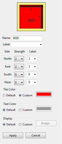
- It is now time to create your SEED tile. If you've completed the TAS Your first tile assembly tutorial this will be no problem. As the name SEED suggests, this is the point from which your TAS will assemble. For now you can think of the SEED as the origin of a 2 dimensional grid.
- The attributes of your SEED tile will be as follows:
X-Axis tiles
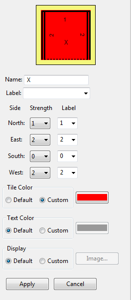
- Again, right click the Tiletype editor and click Insert New. The tile name will be X. Before you move on answer these questions:
- For each side of X, what is the strength of the glue?
- How will each side of the tile X be labeled?
- Look at the picture of the SEED tile, along the East edge there is a glue of strength 2. Recall that for this exercise we are thinking of the SEED as the origin of a graph, where the East edge represents the x axis. If we then place an X tile along the East edge of the SEED, then the Western edge of the X tile must also have a glue strength of 2. Because we want our assembly to grow indefinitely, we also give the Eastern edge of X a glue strength of 2.
- The attributes of your X tile will be as follows:
Notice that the North edge of the X tile has a glue strength of 1. This is to give the interior of the assembly a place to bind.
Y-Axis tiles
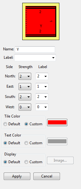
- The Y tiles will bond to the Northern edge of the SEED and will represent the y axis. The Y tile will have the same values as the X tile but rotated 90 degrees clock wise. When you need to create a new tile in TAS that is a rotation of a tile you've already made there is a convenient shortcut you can use.
- Copy and paste the X tile that is in your Tiletype editor. The new tile should have a name of X(2). Right click X(2) and select Rotate(CW) -> 90 degrees.
- After you change the name of X(2) to Y the attributes of your Y tile will be as follows:
At this point it is a good idea to load SEED, X, and Y into the Simulation Window and make sure they assemble as expected. It should look like this:
Sierpinski Triangle tiles
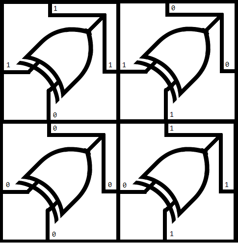
- There are four more tiles to define. To build the Sierpinski triangle we can think about the next four tiles in terms of a double input XOR gate. The two unique input edges of the tile are along the West and South edges, while the output will be expressed along the North and East edges. All of the glues created in this step should be of strength 1.
- Use the skills you learned to create SEED, X, and Y to make the last four tiles that express the logic in the XOR to Tiles picture.
-
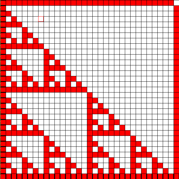
Finally, load the current tile set into the simulator, place a SEED tile and fast forward the assembly. Your results should look like this:
Note that the terminal assembly would actually continue infinitely far up and to the right.
